Monday, 14 March 2016

Sorting Algorithms (Bubble and Shuttle)

Sorting algorithms are needed in order to produce a list in numerical order. this improves efficiency for searching the algorithm

Google sorts webpages by page links (this is how many references a page gets on websites and social media). This process allows webpages to be stored by relevancy.

Bubble Sort
 
Summary
 It works by repeatedly stepping through the list to be sorted, comparing each pair of adjacent items and swapping them if they are in the wrong order. The algorithm gets its name from the way smaller elements “bubble” to the top of the list. This is the least useful sorting algorithm
One final sweep is needed of the whole list so that the list can be checked to see if it is in the right order.
- Has a quadratic order - this is for time complexity of O(n^2)

Advantage – simple to implement.

Disadvantage – inefficient for large lists. The big O time complexity for bubble sort is n^2, this means it is extremely slow.
 

Description of how a bubble sort works

·         Start from the first element to the last

·         Compare each pair of elements and swap their positions if necessary

·         This process is repeated as many times as necessary, until the array is sorted (We know when the array is sorted because there will have been no swaps in the last comparison of all pairs of elements.)

·         After the first pass the last element of the list is sorted so no need to compare again.

·         After the second pass - last two elements sorted, third pass – last three etc…
 
The larger value will always end up at the end of the list, they will be moved there individually
One final sweep is needed of the whole list so that the list can be checked to see if it is in the right order.
 

Algorithm for Bubble sort:
 
Subprogram BubbleSort(aList)
        exchanges = True
        passnum = length of aList – 1
        while passnum > 0 and exchanges == True
           exchanges = False
           for index = 0 to passnum
                if aList[index] > aList[index+1]
                     exchanges = True
                     temp = aList[index]
                     aList[index] = aList[index+1]
                     aList[index+1] = temp
           passnum = passnum – 1
 
Insertion Sort
 
Summary
We can divide a list into a sorted part and unsorted part. Initially the first element is the only
 element in the sorted part then as you work through sorting the second to the last element the sorted part grows. An insertion sort works by taking elements from the unsorted part and inserting them in their correct position into the sorted part. It is similar to the bubble sort however we do not mover step by step, you gather one element and then sort it to its exact place through swapping if needs be.

Advantages – Insertion sort is a simple sorting algorithm and relatively efficient for small lists and mostly-sorted lists. It is faster than the bubble sort.  It’s relatively fast for adding a small number of new items periodically. Large saving compared to the bubble sort.
Reasonably simple code. Good for smaller lists. Works very well when the lists is nearly sorted
Very memory efficient - it only needs one extra storage location to make room for the moving items.

Disadvantage – inefficient for large lists.

The Big O time complexity of insertion sort is O(n^2)
 
Description of how an insertion sort works:

It works the way you might sort a hand of playing cards:

·         We start with an empty left hand [sorted list] and the cards face down on the table [unsorted list].

·         Then remove one card [element] at a time from the table [unsorted list], and insert it into the correct position in the left hand [sorted list].

·         To find the correct position for the card, we compare it with each of the cards already in the hand, from right to left.

Note that at all times, the cards held in the left hand are sorted, and these cards were originally the top cards of the pile on the table.
 
Quicksort 
 
Summary
 A quicksort is a recursive sorting algorithm. The idea behind quicksort is to divide and conquer. First split the list into two parts, one part containing values less than a pivot value, the other containing values greater than this pivot value. In the algorithm below the first item in the unordered list is used as the pivot value. The same process is now applied to each part list, repeatedly, until the parts contain just one value. Joining the part lists back together produces the ordered list. This is a divide and conquer algorithm!

Works by repeated partitioning the list, it chops up the list based on a pivot (a element/ point in the list)
The best pivot is the middle value however that takes a very long time so usually in quick sort it is a random value.
When the pivot is selected all the elements on the left will be less than the pivot and all the elements on the right will be greater than the pivot.
Work in from each end of the list to put the numbers on the correct side of the pivot. 

Advantages – can be much faster than bubble sort and insertion sort.
Can work well on sorting through large lists.

Disadvantage – This process is inefficient in terms of memory for very large lists due to recursion (the stack can grow large with all the return addresses, variables etc. that have to be stored for each recursive call). Sometimes it can grow too large causing a stack overflow (out of stack memory) error.
 
Time complexity of Big O is O(nlogn)
 
Description of how a quicksort works:

·         If the first pointer is less than the last pointer (if there are elements in the list) then:

·         Pick an item within the list to act as a ‘pivot’. The left-most item is a popular choice.

·         Split the list into two parts – one list with items equal to or larger than the pivot item and the other list contains items smaller than the pivot.

·         Repeat this process of splitting each list into two parts until all the parts contain just one value.


This is where recursion is used to quicksort until there is only one element left in the list.

 Generally recursive the algorithm will stop when a value is 0 or 1 in the list.

Thursday, 10 March 2016

CPU Architecture

Components of a CPU:
Based upon the Von-Neuman machine-stored program approach. Where both the data and the programs are stored in the main memory


The Fetch- Decode- Execute cycle:

Fetch - The next instruction is fetched from main memory
Decode- The instruction gets decoded and signals produced to control other components such as the ALU
Execute - The instruction gets executed (carried out)

Registers:
A register is a small block of memory usually around 8 bytes which is used as temporary storage for instructions as they are being processed, these will run at the same speed as the processor. Machine code instructions can only work if they are loaded into registers.

General purpose register are used as programs run to enable calculations to be made or can be used for any purpose the programmer requires. Special purpose registers are crucial to how the processor works. The number of these registers in a CPU varies depending on the architecture.
The most important of these are:
  • Program counter- This holds the address of the next instruction to be fetched decoded and executed. It's value will be automatically incremented by 1 as the current instruction is being decoded. If a branch command is used the program counter will not be incremented by 1 as these commands are used to create loops.
  • Memory address register- This holds of address of the current instruction that is to be executed. It points to the relevant location in memory where the required instruction is. This value is simply copied from the program counter.
  • Memory data register- This can hold both instructions and data. At this stage the instruction has been fetched and is being stored here. The instruction is copied from the memory location pointed to by the memory address register. e.g.. LDA 103
  • Current address register-
    This is used to store the current instruction that is to be decoded and executed, and is copied from the MDR. As this instruction is being executed, the next instruction is being fetched into the MDR. e.g. LDA 103. As this is being decoded, as soon as it is being decoded the program counter is increased/incremented. The example instruction
    is telling the processor to load the value in the memory address 103 into the accumulator.
  • Accumulator- is used by instructions that require a calculation and may update or use the value in the accumulator. For example adding two values will make use of the accumulator. Results of calculations in the accumulator may be used as part of the next calculation.
The Control Unit:
The control unit is in control.
It coordinates all of the fetch decode execute activities. At each clock pulse, it will control the movement of data and instructions between main memory and the CPU etc. Some instructions may take less time than a single clock cycle but the next instruction will only start when the processor executes the next clock cycle.

The Status Register (SR):
Stores a combination of bits to indicate the result of an instruction. For example an overflow error which will be set the value of a bit to indicate a negative result. It also indicates whether an interrupt has been received.

The Arithmetic Logic Unit:
The Arithmetic Logic Unit carried out comparisons or mathematical operations required by an instruction that is executed. Calculations include floating point multiplication and integer division while logic operations include comparison tests such as greater than or less than required by instructions that are executed.


Wednesday, 9 March 2016

Little Man Computer

The basic commands used within LMC:


LMC Homework:

Task 1:
INP - the first value is inputted
STA FIRST - the input is stores in the memory address FIRST
INP - the second value is inputted
ADD FIRST - Add the value in the memory address FIRST to the second value inputted
OUT - the result is then outputted
INP - the third value is inputted
SUB FIRST - Subtract the value in the memory address FIRST from the third value inputted
OUT - the result is outputted
HLT - Finish the program

FIRST DAT - Declare FIRST as the next available memory address

Task 2:
INP - the first value is inputted
STA FIRST - Store the value in the memory address FIRST
INP - input a second value
STA SECOND - Store the second value in the memory address SECOND
LDA FIRST - Load the value in the memory address FIRST
OUT - Output this value (found in FIRST)
LDA SECOND - Load the value in the memory address SECOND
OUT - Output this value (found in SECOND)
HLT - Finish the program

FIRST DAT - Declare FIRST as the next available memory address
SECOND DAT - Declare SECOND as the next available memory address (after FIRST)

This program in LMC accepts inputs of values and then remembers them and stores then in different mailboxes to then be accessed at a later time.

Tuesday, 8 March 2016

Processor notes

Processors:
  • The processor is the brain of the computer
  • It carries out the mathematical and logical operations which are needed for programs and activities within the CPU
  • It is one of the most expensive parts of a computer.

Machine Language:
This is the Language that the processor or CPU can understand.
This type of code is understood by the CPU and Processor and it's called machine code.

Source code;
Source code is written and understandable for humans, it is a high level language.
In order for machine code to be created from the source code a compiler is needed. this coverts the high level language into the machine code.
compiler converts the source code into machine code.

Important information about processor architecture;

Each processor architecture has its own unique instruction set
The compiler has to know the target architecture (in the process of converting source code into machine code)

The length of the code varies when it is converted by the compiler:
For example - 1 line of source code may be multiple lines of machine code.

Machine code is binary versions of instructions
  • Opcode -The action or operation to be performed on a set of data
  • Operand- the data itself or the location where the data is stored

Monday, 7 March 2016

Revision summary notes Logic Gates

Logic Gates;

What is a logic gate:
Logic Gates perform a logical operation one or more logical inputs and produces a single logical output. Logic gates are implemented using diodes or transistors acting as electronic switches. Billions of gates are in a computer.

The Three main types of logic gates:
- AND - outputs true if both inputs are true
- OR - outputs true if either are true
- NOT - outputs the inverse of the input


Boolean Algebra:
Logic gates can be represented using boolean algebra. These are statements containing letters and symbols to represent the type of gates
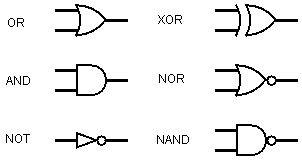
They all have names and symbols.
A proposition is a statement that can be defined as either true for false, for example 'Let P be it is raining' as this can be either true or false. These statements are booleans as they only have 1 answers whereas 'what is the weather' can have many answers.

Conjunction:
The informal term is AND, it behaves the same as the AND logic gate. For the statement to be true all inputs must also be true. When used in boolean algebra is has the symbol ^.

The truth table for conjunction is as follows:
P
Q
P AND Q
T
T
T
T
F
F
F
T
F
F
F
F


Disjunction:
The informal term is OR. Either of the inputs can be true for the whole statement to be true. When used in boolean algebra it has the symbol ∨.

The truth table for disjunction is as follows:
P
Q
P OR Q
T
T
T
T
F
T
F
T
T
F
F
F

Logic Gates perform a logical operation one or more logical inputs and produces a single logical output. Logic gates are implemented using diodes or transistors acting as electronic switches. Billions of gates are in a computer.

Types of logic gates:
- AND - outputs true if both inputs are true
- OR - outputs true if either are true
- NOT - outputs the inverse of the input


Boolean Algebra:
Logic gates can be represented using boolean algebra. They all have names and symbols. A proposition is a statement that can be defined as either true for false, for example 'Let P be it is raining' as this can be either true or false. These statements are booleans as they only have 1 answers whereas 'what is the weather' can have many answers.

Example of boolean algebra:
x=a^b


Conjunction:
The informal term is AND, it behaves the same as the AND logic gate. For the statement to be true all inputs must also be true. When used in boolean algebra is has the symbol ^.

The truth table for conjunction is as follows:
P
Q
P AND Q
T
T
T
T
F
F
F
T
F
F
F
F


Disjunction:
The informal term is OR. Either of the inputs can be true for the whole statement to be true. When used in boolean algebra it has the symbol ∨.

The truth table for disjunction is as follows:
P
Q
P OR Q
T
T
T
T
F
T
F
T
T
F
F
F


Negation:
The informal term is NOT. It gives the reverse of the input. It has the symbol ¬ and will apply to the proposition following it.

The truth table for negation is as follows:
P
NOT P
T
F
F
T


Equivalence:
The informal term is equality. It has two possible symbols ↔ or ≡. It means that the truth on both sides are equivalent. For this to be true both sides must evaluate to the same truth value.

The truth table for equivalence is as follows:
P
Q
P ↔ Q
T
T
T
T
F
F
F
T
F
F
F
T
There is no logic gate for equivalence.

Exclusive Disjunction
The informal term is XOR. It has a symbol of ⊕. It will only output true if both values are true or both values are false. The logic gate is shown earlier.


Thursday, 3 March 2016

Processors

1.1 Structure and function of the processor
1.1.2 Types of processors

Context:
  • The processor is the brain of the computer, it carries out the mathematical and logical operations which are necessary.
  • It is one of the most expensive parts of a computer. Upgrading the processor will greatly improve the performance.
  • They can be found in mobile phones and washing machines and all electronic devices. The way in which they are constructed changes rapidly.
  • Processor designs are extremely complex.
Things that can be upgraded:
RAM- This will give the computer more main memory
Graphic cards-
Usually people swap a hard disk drive for a SSD
Purchasing a CPU with higher cores- this isn't generally done due to the cost and more technical acquisition is needed to improve and replace a CPU.

Creating processor architecture, specialists will have to design a specific circuitry.
Silicon discs will then be produced by melting and finely slicing- producing crystals.
Processor are produced in a special room called a clean room

It takes a few minutes for a processor to work at 300 centigrade.

Machine Language:
This is the target of which the processor or CPU can understand, this type of code is called machine code.
Source code is written and understandable for humans, it is a high level language.
In order for machine code to be created from the source code a compiler is needed. this coverts the high level language into the machine code.
A compiler converts the source code into machine code.

Each processor architecture has its own unique instruction set
The compiler has to know the target architecture (in the process of converting source code into machine code)

The length of the code varies when it is converted by the compiler:
For example - 1 line of source code may be multiple lines of machine code.


Machine code  is the binary representation of an instruction, that is split into to distinct parts :
  • Opcode -The action or operation to be performed on a set of data
  • Operand- the data itself or the location where the data is stored
Assembly language:
This is the use of text (small mnemonics) to represent machine code
More simplified than source code

The size of instructions differ from architecture to architecture

Every instruction that a processor architecture can understand has a unique binary representation/ value, which is known as an Opcode
When executed the Opcode is used to determine which instruction to execute (what action it is to perform)


An example of the Opcode and what will happen when execution occurs:
Opcode
Assembly mnemonic
Description
000 0001
MOV
Moves a value to a register
000 010
ADD
Adds a value and stores in ACC (accumulator)
000 100
SUB
Subtracts a value and stores in ACC (accumulator)
001 000
MLT
Multiplies a value and stores in ACC (accumulator)


Assembly code is the step above machine code, allowing the coder to write code using mnemonics which represent machine code instructions.
When converting assembly code to machine code you must use an assembler
Each assembly code instruction has a one- to- one mapping.

Mnemonic Instruction Alternative mnemonics accepted
ADD Add
SUB Subtract
STA Store STO
LDA Load LOAD
BRA Branch always BR
BRZ Branch if zero BZ
BRP Branch if positive BP
INP Input IN, INPUT
OUT Output
HLT End program COB, END
DAT Data location


An xx in the Opcode refers to the data part (operand) of the instructions (only if required as not every instruction needs data) For example in order to add, you first need to know what they are adding.
Mail boxes can be referred to directly or indirectly, through the use of labels. A label is a text symbol that represents a mailbox making coding in LMC easier.
When a label is used to represent a mailbox the LMC assembler assigns a suitable mailbox as the code is assembled

Little Man Computer:


The Little Man Computer step by step:

Instruction Fetch

As a first step in the fixed routine, the "little man" must get the instruction telling him what he should do next. The input is taken and stored in the accumulator
  1. he reads and remembers the Mailbox number currently displayed as the Counter value
  2. he goes over to the Mailbox with the Mailbox number that he is remembering, reads the 3 digit value in that Mailbox, and remembers it as the current Instruction value (forgetting any previous Instruction value that he might have been remembering

Counter Increment

The incrementing of the Counter must occur before instruction execution, as will become obvious when we look at instructions whose execution modifies the value in the Counter.
  1. the "little man" pushes a button which increments the Counter value so that it contains the Mailbox number of the sequencially next Mailbox.

Instruction Execution

  1. the "little man" compares the first digit of the Instruction value that he is remembering with the list of values in the "Instruction Set Table" to find out what he should do.
  2. he then follows the directions given in the Instruction Set Table that correspond to the first digit of the Instruction value.


Comparison Operators


==
Equal to

!=
Not equal to

<
Less than

<=
Less than or equal to

>
Greater than

>=
Greater than or equal to

Arithmetic Operators
 

+ Addition e.g. x=6+5 gives 11
- Subtraction e.g. x=6-5 gives 1
* Multiplication e.g. x=12*2 gives 24
/ Division e.g. x=12/2 gives 6
MOD Modulus e.g. 12MOD5 gives 2
DIV Quotient e.g. 17DIV5 gives 3
^ Exponentiation e.g. 3^4 gives 81